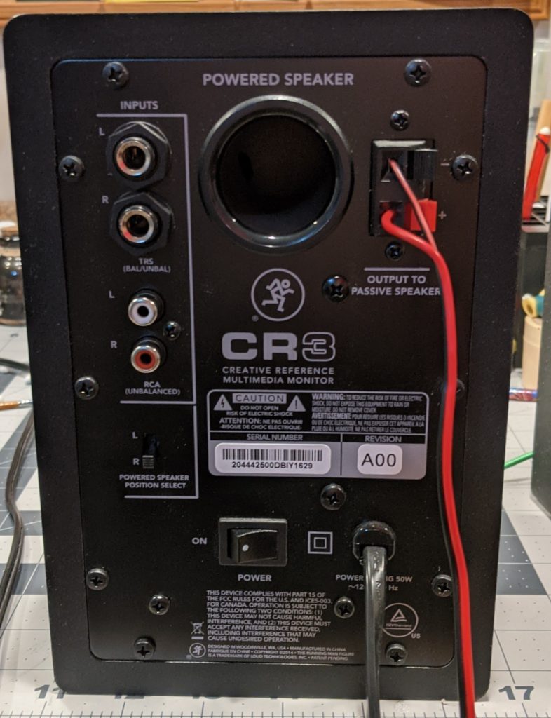
Problem: No sound coming out of the speakers. In the beginning the sound would come and go. Then the sound stopping became more frequent until being completely mute.
What is working: The headphone output is working fine. With it I could test that the auxiliary input (front panel) is working fine too. Left and right RCA inputs are working. Left and right left and right  6.35 mm (​1â„4 inch) inputs are working.
From the outside the only problem seems to be the speaker.
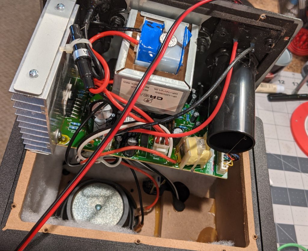
The cause: After some research I found that this is a common issue for Mackie CR3 Studio Monitors. The root cause seems to be the amplifier chip TDA7265. This chip works fine initially but after some months or years it starts malfunctioning sending a mute signal (output 5) to the board which mutes the speakers. This mute signal should only be triggered when a headphone jack is inserted however in the malfunction the signal is sent continuously.
Solution: cut the ping 5 with small cutting pliers. This stopped the mute signal but also removed the feature of muting the speakers when headphones are plugged. As this worked for me I could replace the TDA7265 chip (around $5) but I will not do that now.
Alternatives: here are some alternative solutions that did not work for me but I read that worked for some.
Blowing air into the inputs to remove dust and debris.
Quickly removing and inserting and inserting the auxiliary jack.
Quickly removing and inserting and inserting the headphones jack.
Conclusion: Don’t buy these speakers. I got it in a bundle deal with some audio gear I bought about three years ago. Speakers should not fail in only three years. The design of this thing is flawed. It heats too much and components start to fail. The amplifier chip seems to be a common issue but when researching this I found switches, I also saw switches, diodes, capacitors, and resistances failing. Even after I fixed it I was hearing some cracking noise in some frequencies.
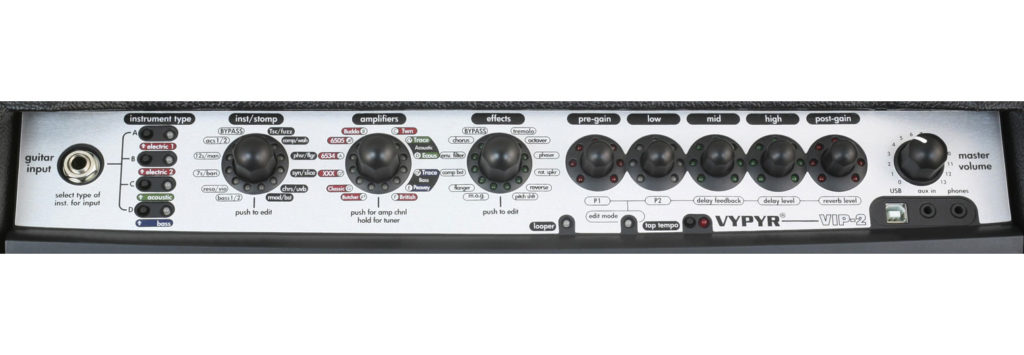
Press the amplifiers knob to select the clean (green) mode of the classic amplifier.
Press the inst/stomp knob. You are now in the edit mode and the edit mode led (red) is on.
Turn the delay feedback knob to zero.
Turn the delay level knob to zero.
Turn the reverb level to zero.
Press the inst/stomp knob again. You are now out of the edit mode and the edit mode led is off.
Turn the pre-gain knob to the middle.
Turn the low knob to the middle.
Turn the mid knob to the middle.
Turn the high knob to the middle.
Turn the post-gain knob to the middle.
To always have this patch when the amplifier starts, save it to the bank A preset 1 (red). On the instrument type column of buttons, press and hold the first button (A electric 1) until the red led blinks once and comes back on.
In this pixel art rendition I replaced the the characters of Super Mario Bros. for female characters becoming Super Maria Sis. in the tittle.
Mario became Maria just because it’s a single letter change and it works well. Marissa would also have worked.
Luigi became Ligia. Other candidates were Lucia and Luiza. In Italian the feminine name for Luigi is Luigina. Luigi is one of the many Italian forms for the german name Ludwig, which in French becomes Louis. So Luise would have been another candidate. In Portuguese LuÃs, Luis, or Luiz and their feminine version Luisa, LuÃza. I choose Ligia because of the “G” sound.
Slendor. 42 inch (106.68 cm) long, 9 inches (22.86 cm). 7 inches (17.78 cm) aluminum trucks. 9 layers cold-pressed maple deck. Wheels are made of Polyurethane (PU), have a 85A durometer hardness and ABEC-9 bearings, 70mm (2.75 inch)
# Get the HTML page content
from urllib import request
html = request.urlopen("https://silveiraneto.net").read()

# Get the title tag
from bs4 import BeautifulSoup
title = BeautifulSoup(html, 'html.parser').find('title')

print(title.string)
This uses the XML/HTML library BeautifulSoup . This could also be done using regex but playing with HTML and regex is usually a bad idea.
For instance, I had an Cyber Acoustics CA-3602FFP 2.1 Speaker Sound System with Subwoofer and Control Pod around without use after I upgraded some equipment100. I’m not going to disagree with anyone who says this is a total overkill for this project. This has a lot of power and a subwoofer. It greatly exceeds the sound needs for old arcades games. However, it was literally accumulating dust in a corner.
Cyber Acoustics CA-3602FFP 2.1 Speaker Sound System with Subwoofer and Control Pod
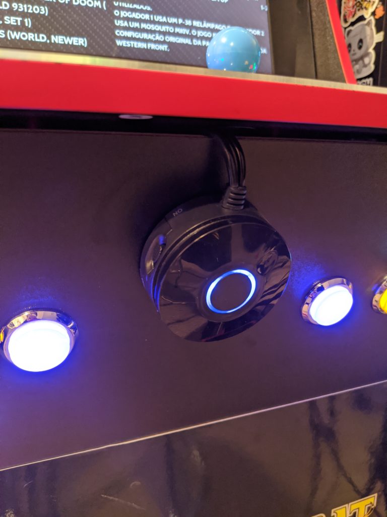
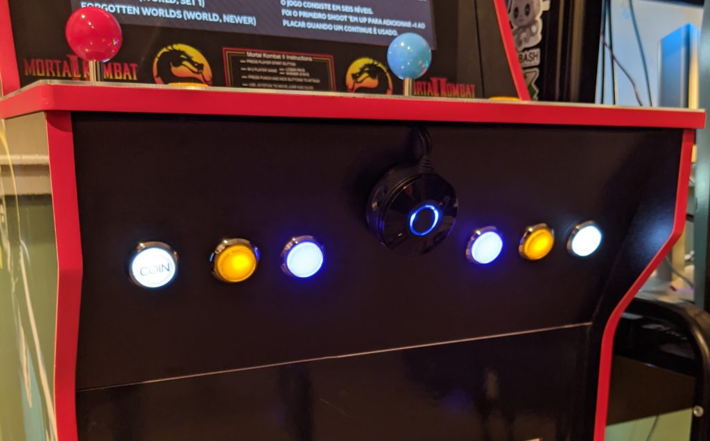
This thing also have this little control pod that is just perfect for this project. It controls the volume using a knob. I absolutely love control knobs. I could write a whole post about knobs. It has a round blue led which goes well with the whole arcade theme. On top of all that, the control pod also has a control for bass, an on/off switch, an auxiliary input and a phone output.
Volume control
Because the wires fit in the gap between the panels no drilling was necessary. Inside the cabinet I just put the subwoofer an the two speakers. I used a double-sided mounting tape to put it in place.
The little blue circle light.
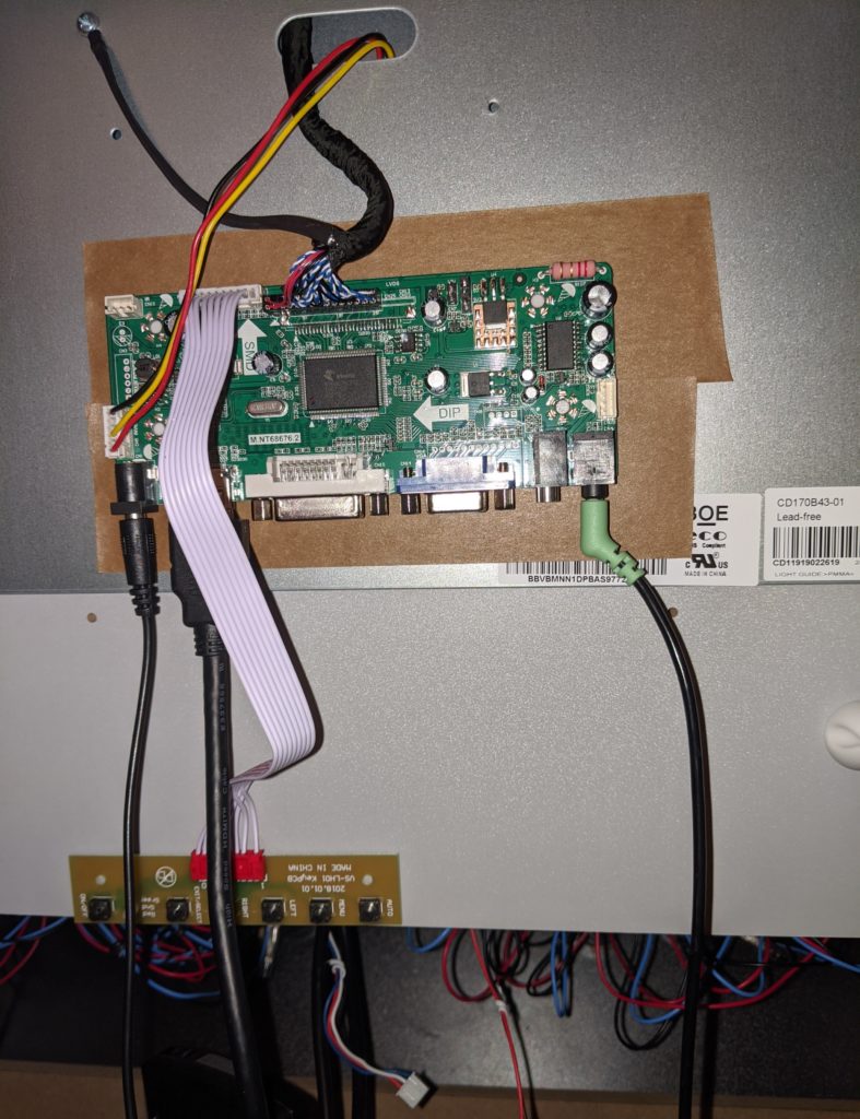
For the sound input I used the sound output from the control board. That is already converting the HDMI sound output. Another solution would be to plug it directly into the Raspberry PI and configure it to output the sound there instead of sending it via HDMI.
Control board to speakers
Lights
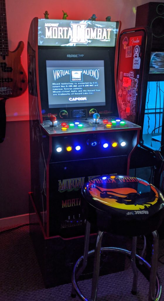
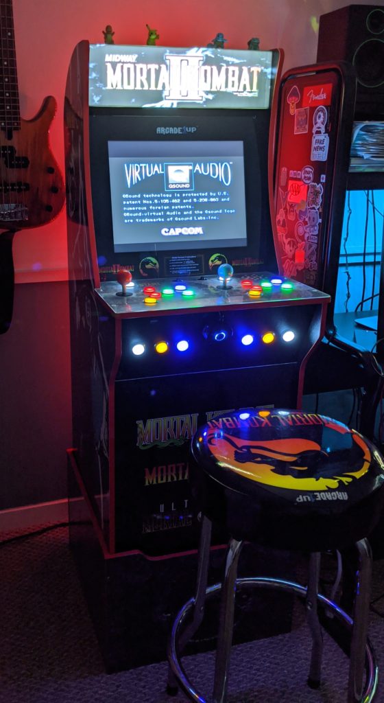
The last thing I added was just some LED strip lights in the back of the machine. It’s just some led multicolor strip lights that I bough a while ago for around 5 bucks. I just let it set to red because it goes well with the vinyl strip it came with.
Really ties the room together.
That’s probably the simplest and cheapest of all the modifications but really adds some ambiance around the cabinet.
Because the lights and everything else are in the same power strip that is behind the same Amazon Smart Plug when I say “alexa turn the arcade on” everything lights up with a lot of colors.
Conclusion
This has been a long and fun project. I have been incrementallychanging parts and adding modifications. It’s slow and it’s not a single weekend project. It’s good to spend time on each iteration and getting a felling of what needs to be improved. There is still some room for a few more lights and maybe a beer holder. Other than that the next changes should be on software.
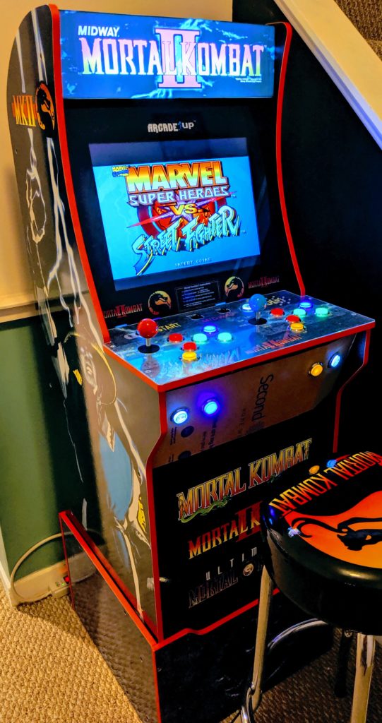
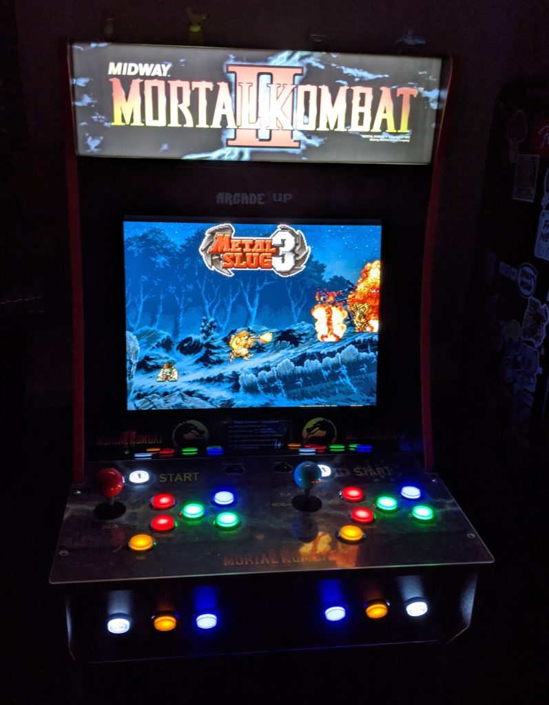
I decided to add a second control deck to this cabinet using the wood panel that already came with the original machine. My initial plan was to add 4 more buttons so each player would have 2 extra buttons for games that requires a lot of buttons.
Prototyping
Before committing to a layout and irreversible woodworking I build a crude but functional prototype out of cardboard.
Cardboard prototype
The prototype was important to realize this was not the layout I wanted. I wanted more buttons. The original control deck has 7 buttons for each of the 2 players. Usually this would be enough but you have to use one of them to the start button and another for coin button. You also need a special button to exit the emulator. That’s 3 out of 7 buttons. Only 4 left for the core gameplay itself. Because this machine should be generic for many types of games I decided to add 3 more buttons for each player so each player has a total of 10 buttons.
The cardboard prototype is an optional step but it was easy and quick to do, it’s fully functional, and provided me some insights for the next steps. I used a piece of cardboard and put the panel J to trace a copy over it using a pencil. Then I cut the cardboard using a craft knife and also cut holes for the buttons. I installed it i the buttons, put the cardboard in the same place of the Panel J, put the wires, and configured the software. I could use the machine like this for some weeks before I moved to the next phase.
Layout
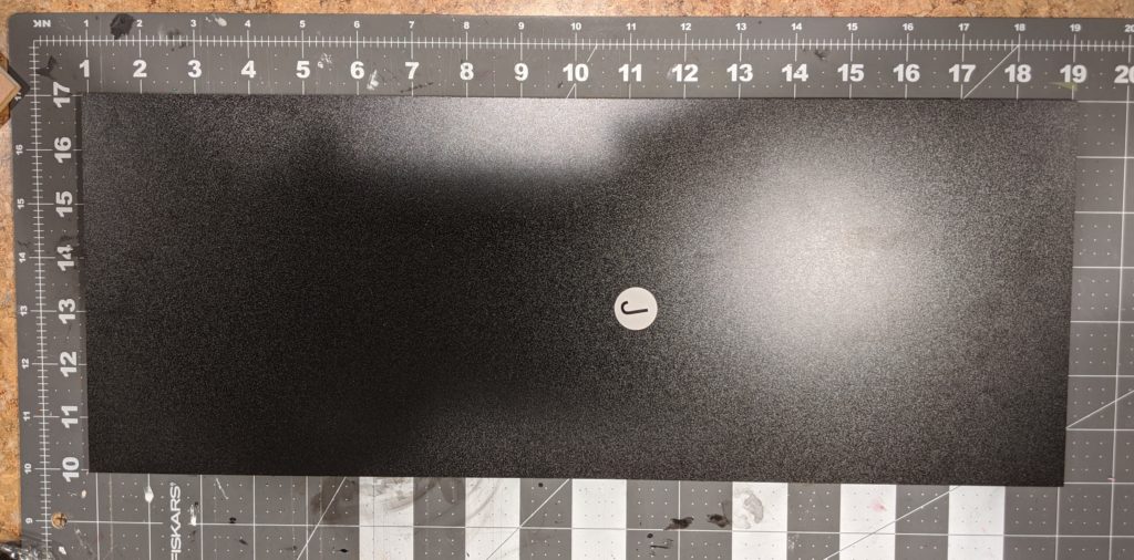
I don’t have a lot of experience with wood so this was my attempt. I had this piece of black coated plywood (45.72 x 17.78 cm ~ 18 x 7 inches) and I wanted to put 6 arcade buttons on it.
46 cm x 18 cm (18 inches x 7 inches)
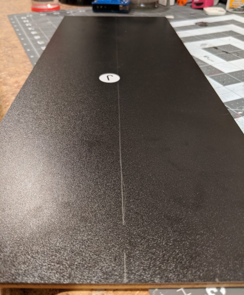
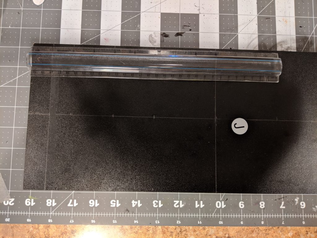
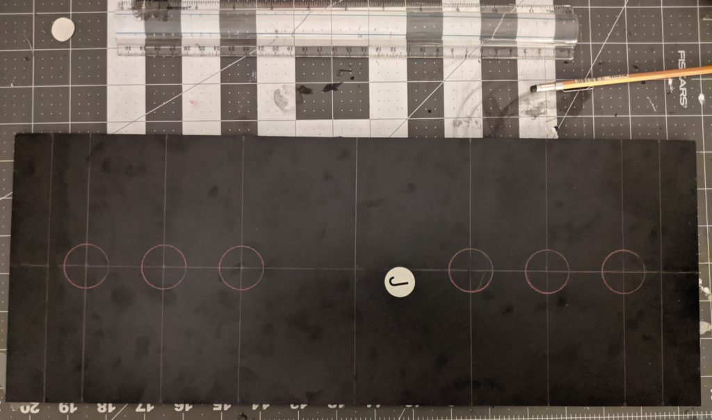
First I needed a layout for the buttons. By using the prototype for a while I wanted the buttons in the middle of the panel. Some margin from the sides. Some space in the middle for some future project. The method I used to make the lines using a mechanical paper and a rule is the following:
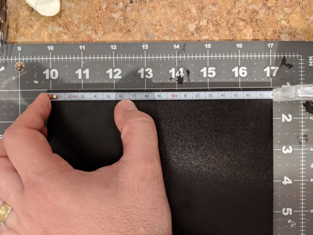
First, I measure the number I want on one side. Here, I wanted a straight line in the middle of the panel. I get the height of the panel (7 inches ~ 17.78 cm) divide it by 2 (3 ½ inches ~ 8.89 cm) and mark it down using a mechanical pencil.
Second, I do the same thing in the opposite side of the panel.
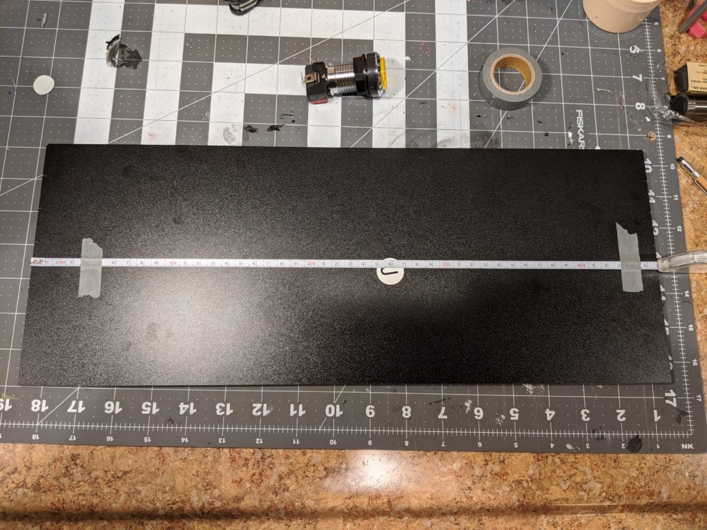
Third, I trace a line between those two points. As I don’t have a rule long enough for this line I used a metal tape measure. Any long straight object will do.
Because I was using a tape measure I used tape to fix it on both side before making the line.
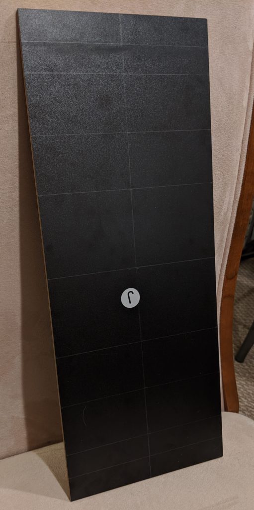
Now repeating this process I got a perpendicular line in the middle of the panel. Then other 2 lines each 1 each away from the border.
Then I did moved another 1 inch to mark where the first button was going to be. This way the first button center is 2 inches away from the border. From this center I moved 2 more inches to find the next center. And then did the same for third center. I repeated the same process for the second player.
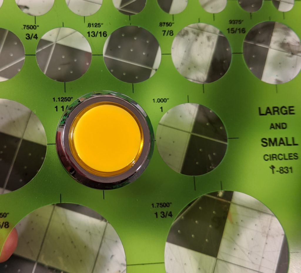
I happen to have this circles template that is very handy here. The circle I need is 1 â…› ” (2.8575 cm) and I could use the template to test if the button fits before committing to the whole size. It fits perfectly. This is the same whole size for the other buttons in this Arcade1Up.
Using red graphite and the circles template I made the circles where the buttons would be. This step is not really necessary but I wanted to be sure this looks okay before doing the holes.
Woodworking
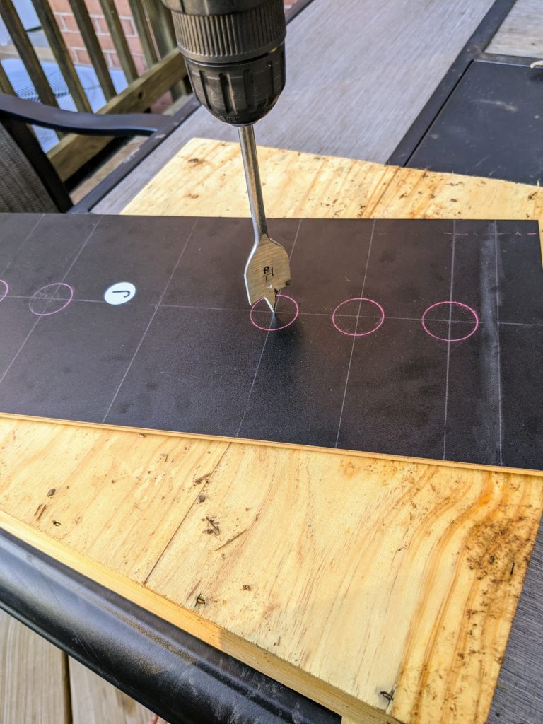
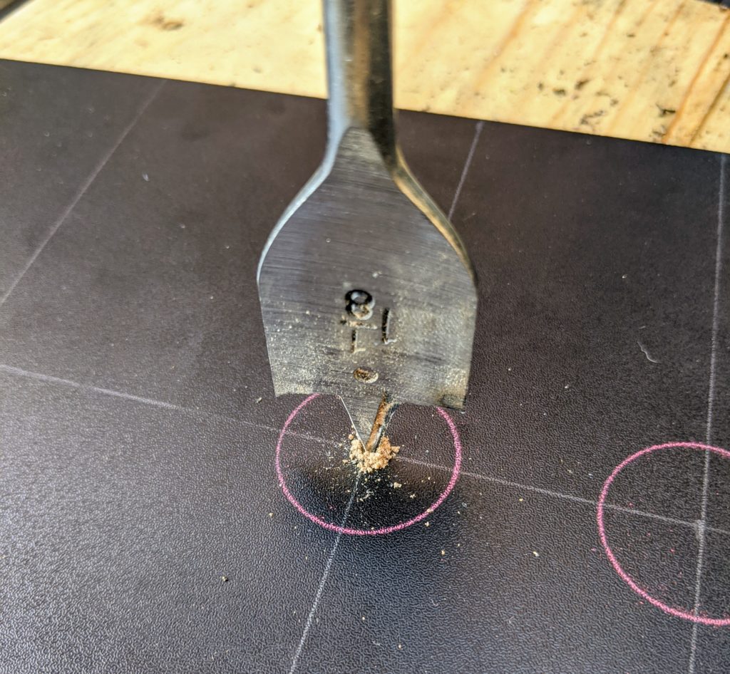
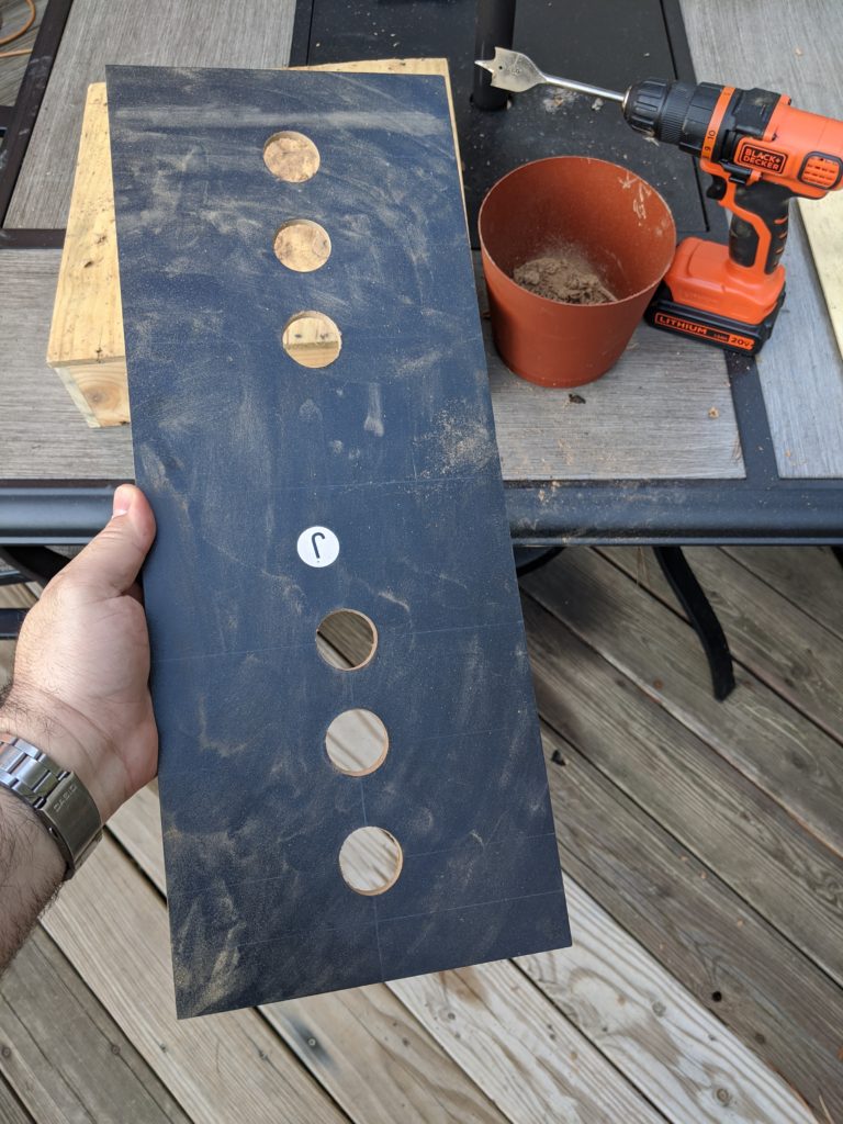
I put a old piece of wood bellow the panel I’m going to drill. This way when I go over the panel I will not hit the table. I’m using a 1 â…› ” spade drill from this drill bit set and a Black & Decker LD120VA drill.
Point of no return on this project.Oh, there is a lot of sawdust. Better do this outside.6 buttons. 6 holes.
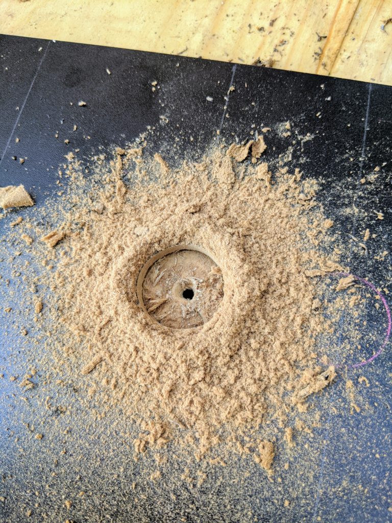
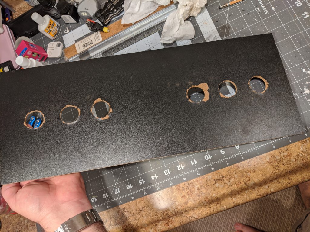
On one side the wholes where clean but in the other side there were these ugly “exit wounds”. As I said, I don’t have a lot of experience with wood. Fortunately this board is the same both sides and I could just clean the side that was supposed to be hidden and use as a front panel.
How could I have avoided this?
Buttons
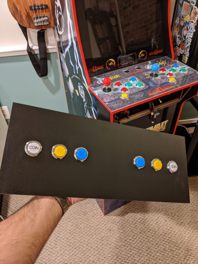
Buttons installation is just like it was on part 2. In total I could use all the buttons that came with the kit.
6 more buttons
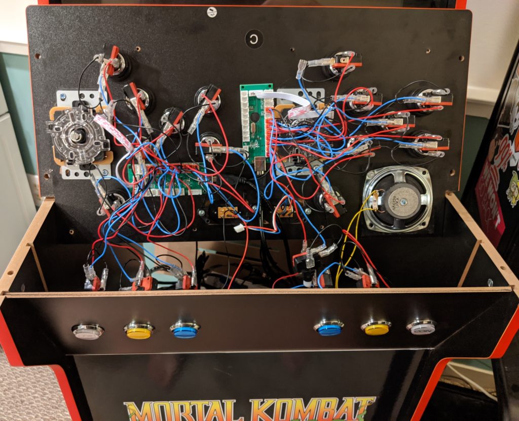
They are close enough from the control board so the wires can reach the connectors. Here I’m glad I did the cardboard prototype because I knew I didn’t need to extend these wires.
No cable management.
As far as configurations go it is the same as in part 2. These buttons behave just like any of the other buttons. For the Raspberry PI this is a computer with two USB joysticks plugged on it. Each with 10 buttons and the directional which is the same as another 4 buttons.
Everything lit.
Conclusion
Now this machine has two joysticks and 20 buttons and 2 joysticks. That is enough to play all the games I want. On the next part of this tutorial I will show how to add better sound and even more lights.