In 2016 I got a Monoprice Select Mini 3D Printer (model number 15365) for $200 USD. That was incredibly affordable for a 3D printer back then. That printer only gave me disappointments. I was never was able to print anything completely with it. My main problem was adhesion. The only help I got was online forums (there was a really active Facebook group about it). Debugging and trying different solutions without any success was not fun. It ended up just accumulating dust and occupying space in a corner.
Years later I found that my local library had working and calibrated 3d printers that I could just use. Just upload a .stl file and they would just email me when the print was ready. Also, for free. I tried it and it worked really well.
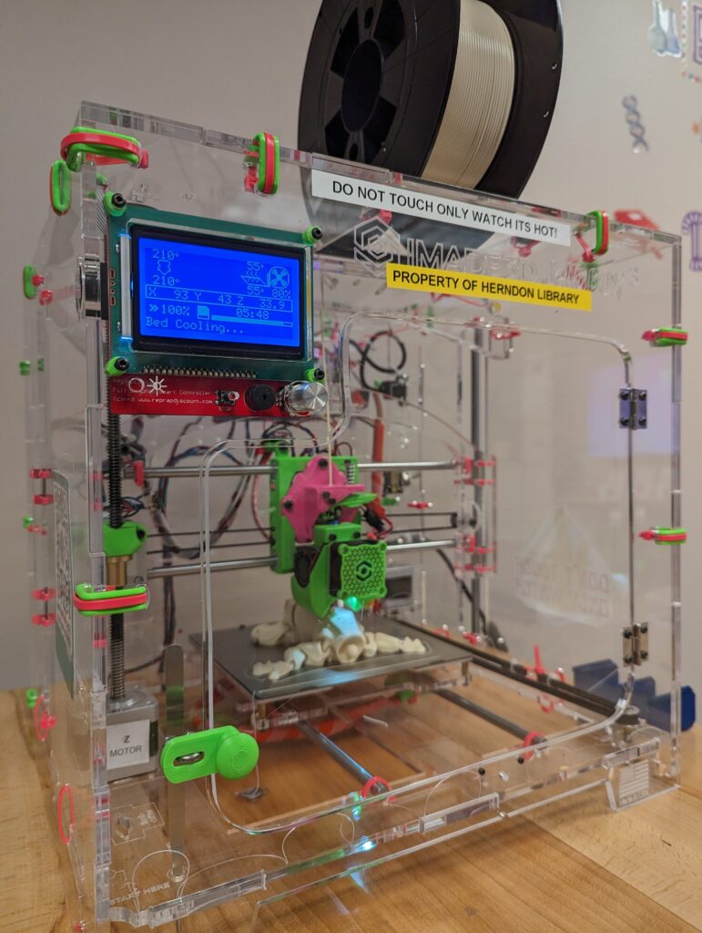
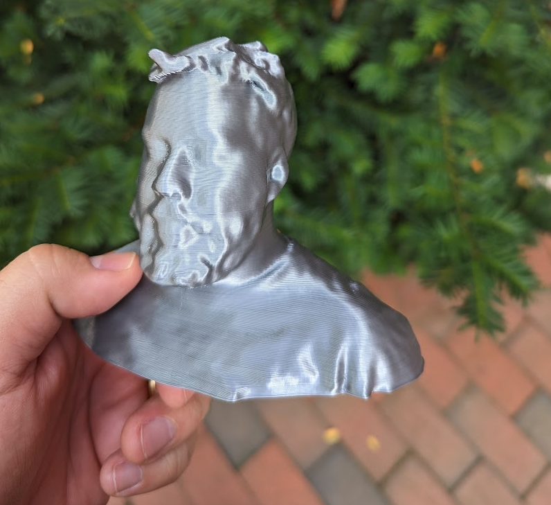
Example of 3D printer available in Fairfax LibrariesMy head, 3d printed at my local library. I had my head 3D scanned by MakerBot in 2014.
So I filled some paperwork and donated my Monoprice Select Mini 3D Printer to the library. They also had a lot of other cool technology programs going on. From now on if I need to print something I know I could just use the library. I promise myself I would not mess with 3D printers themselves anymore.
Now in 2025, someone in the neighborhood was looking to donate their Monoprice Maker 2 Ultimate 3D printer. Just when I thought I was out, they pulled me back in. I got it from his hands, bought a spool of PLA Filament and started playing with it.
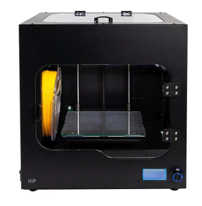
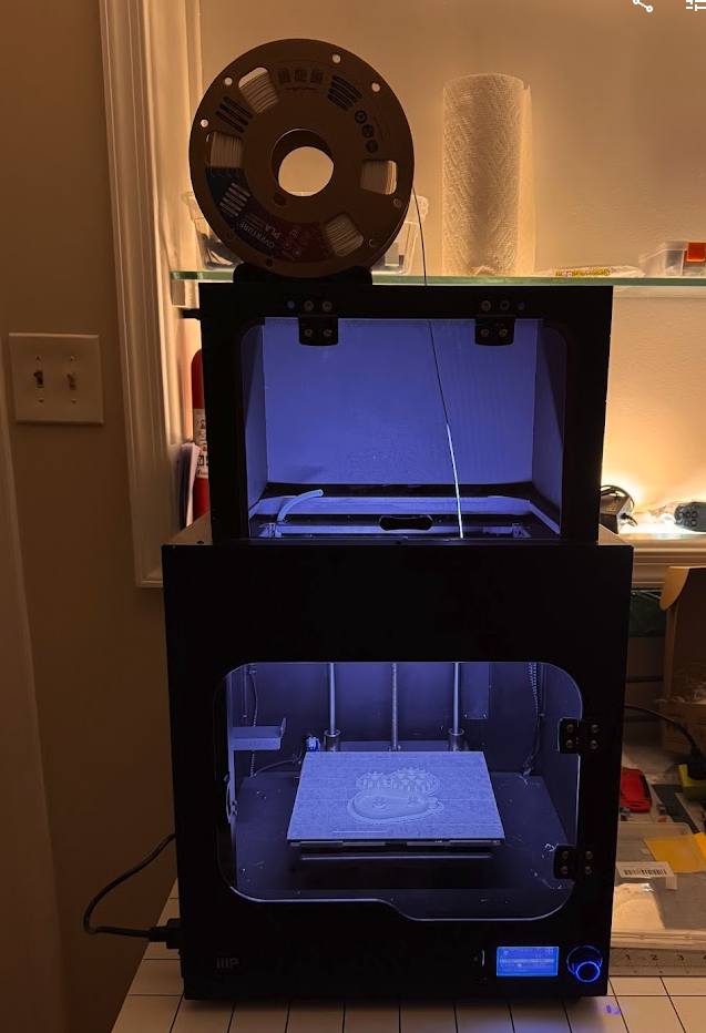
Monoprice Maker 2 Ultimate 3D printer
Monoprice Maker 2 Ultimate 3D printer technical specifications:
Dimensions: 15.0″ x 13.4″ x 16.5″ (380 x 340 x 420 mm)
Weight: 33.1 lbs. (15kg)
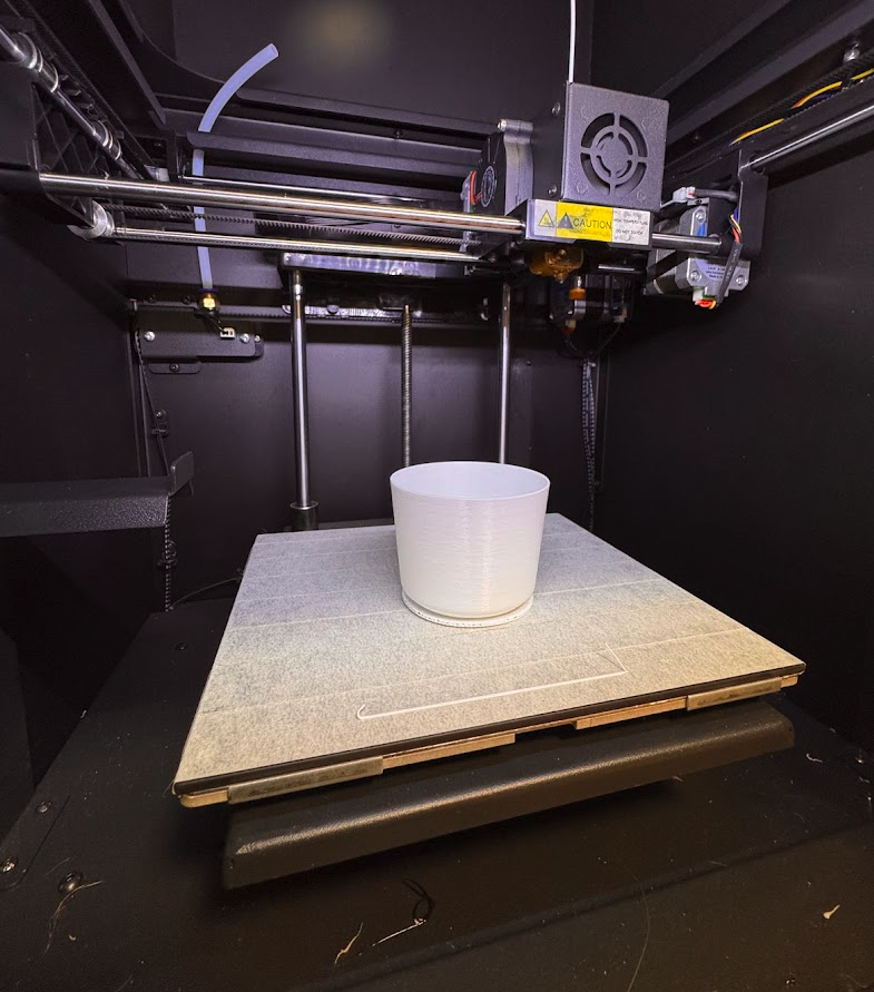
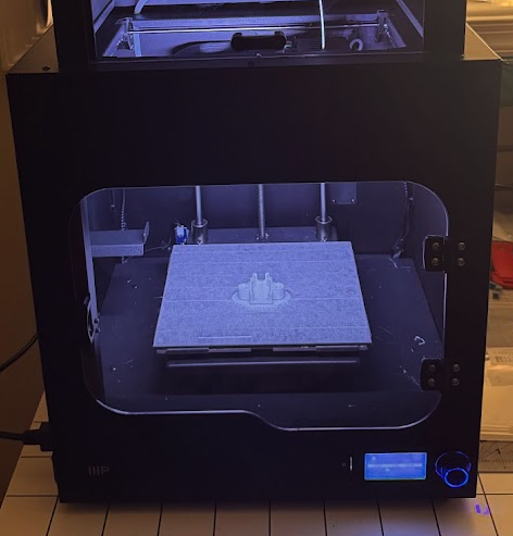
I started just printing whatever gcode it had on its sdcard. My first prints were just adhesion failures again. That’s when my previous experiences from before were handy. I re-applied painters tape on the print bed, then the prints started to get further and further before failing. Then I got my first complete 3d print.
My first 3d print
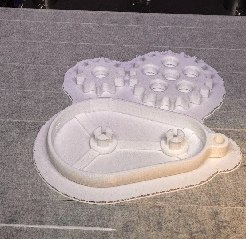
Then I started trying with Thingverse stl objects, cutting them in Ultimaker Cura and printing my own gcodes. Here is the catch: the Monoprice Maker 2 Ultimate is a rebranded Weedo F150s. After I configured Cura to use a Weedo F150s the gcodes produced started to print with success.
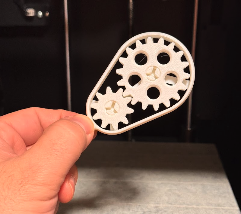
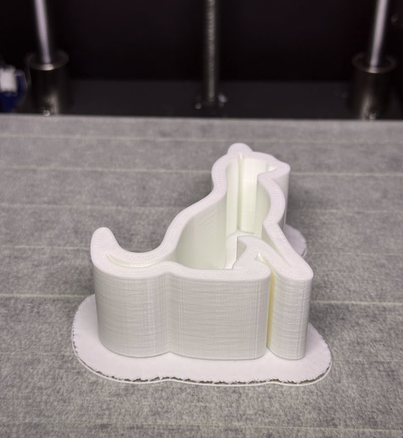
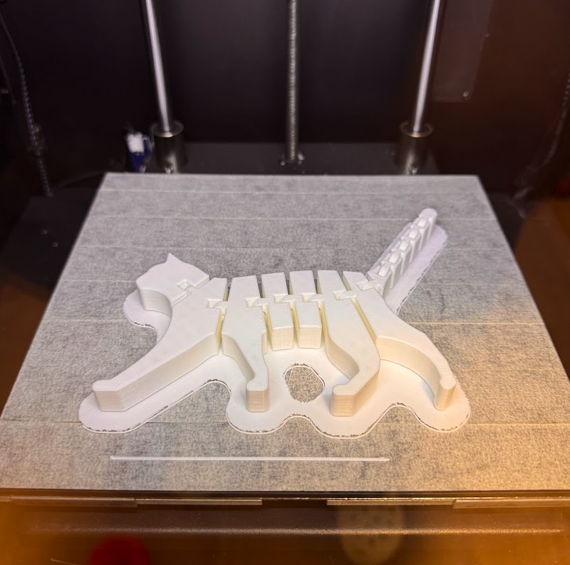
I have now printed this flexi cat that took almost 6 hours. Do you know what I never got it printing correctly? That 3DBenchy that I always tried to print on my first printer. On this one it always causes the printer to shift layers and fail. Surely with some fine tuning of the parameters I can get it right but the lesson learned here is that sometimes a simple vase is a much better goal. Also, sometimes a 3D printer have more success printing larger objects rather than small ones.
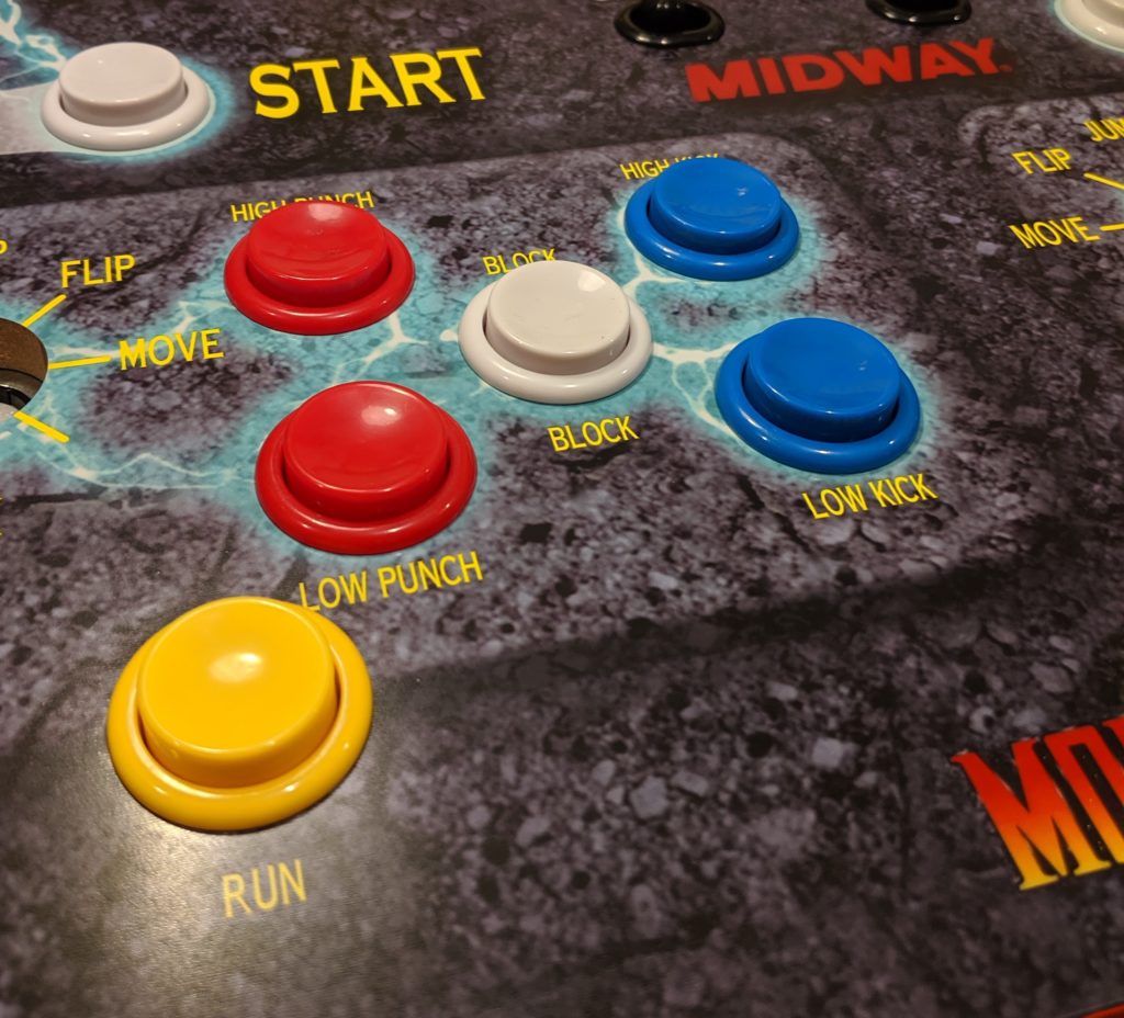
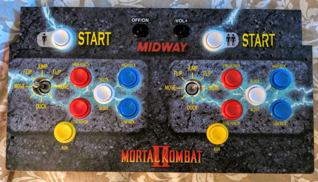
What I’m showing here was done with an Arcade1UP Mortal Kombat but should work for other models with little changes. One of the reasons I choose the Mortal Kombat cabinet was because the number of buttons and their layout.
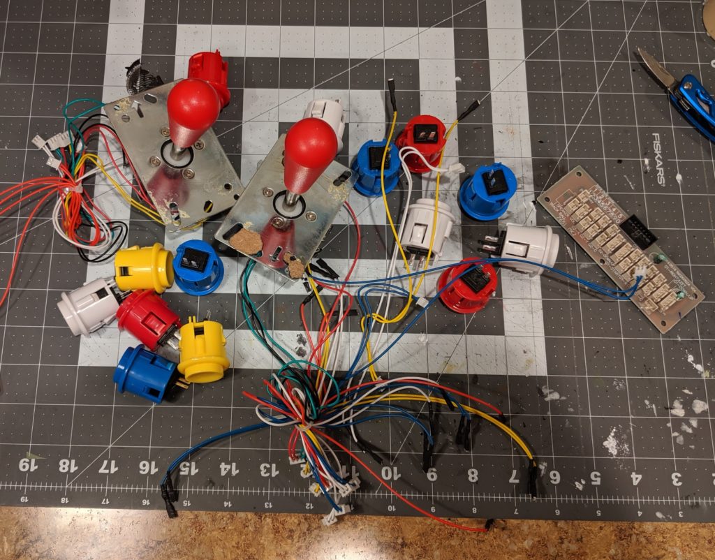
It’s worth noticing that you don’t necessarily need all these parts or these parts in specific. These were the ones I used and most of them were not bought specifically for this project and I could use them because I had around.
Replacing the joysticks and buttons
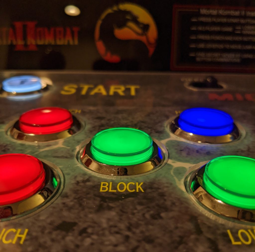
The original buttons on my MK Arcade1Up were a bit ugly and quiet. I want something more flashy and more clickly. I went with this kit on eBay that comes with 20 buttons, joysticks and encoders. The buttons have a LED inside and a round plastic chrome ring around them. They also come with everything necessary to replace the original buttons and they fit in the same 1 â…› ” (2.8575 cm) hole.
Old buttons.New buttons
Step 1. Remove the control deck from the cabinet.
Control deck detached from cabinet
Step 2. Remove the protective black plastic case exposing the wires and circuit boards from the control deck.
Control deck with protection case removedOriginal control deck components
Step 3. Remove all the wires.
Wires removed
Step 4. Remove the buttons. They are a single piece. You just have to press them in their opposite bulges and they will fit to leave the hole in the front panel.
Press…… and push.Old buttons removed
Step 5. Remove the controller board. Just unscrew it and remove it.
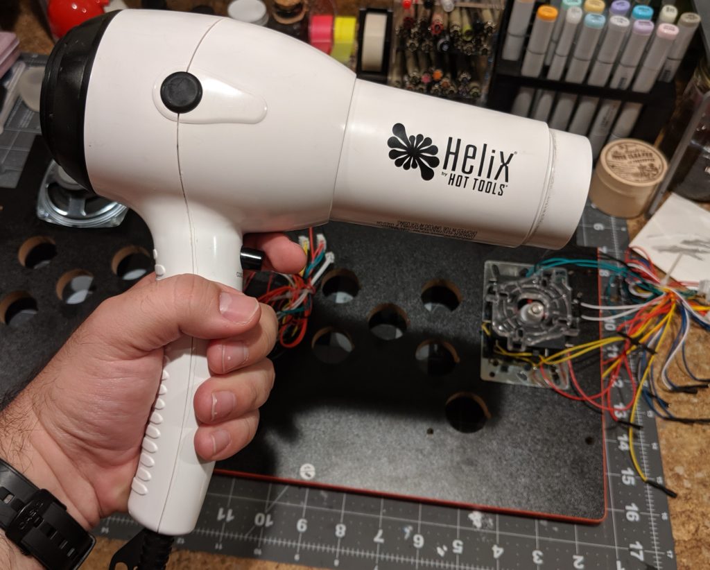
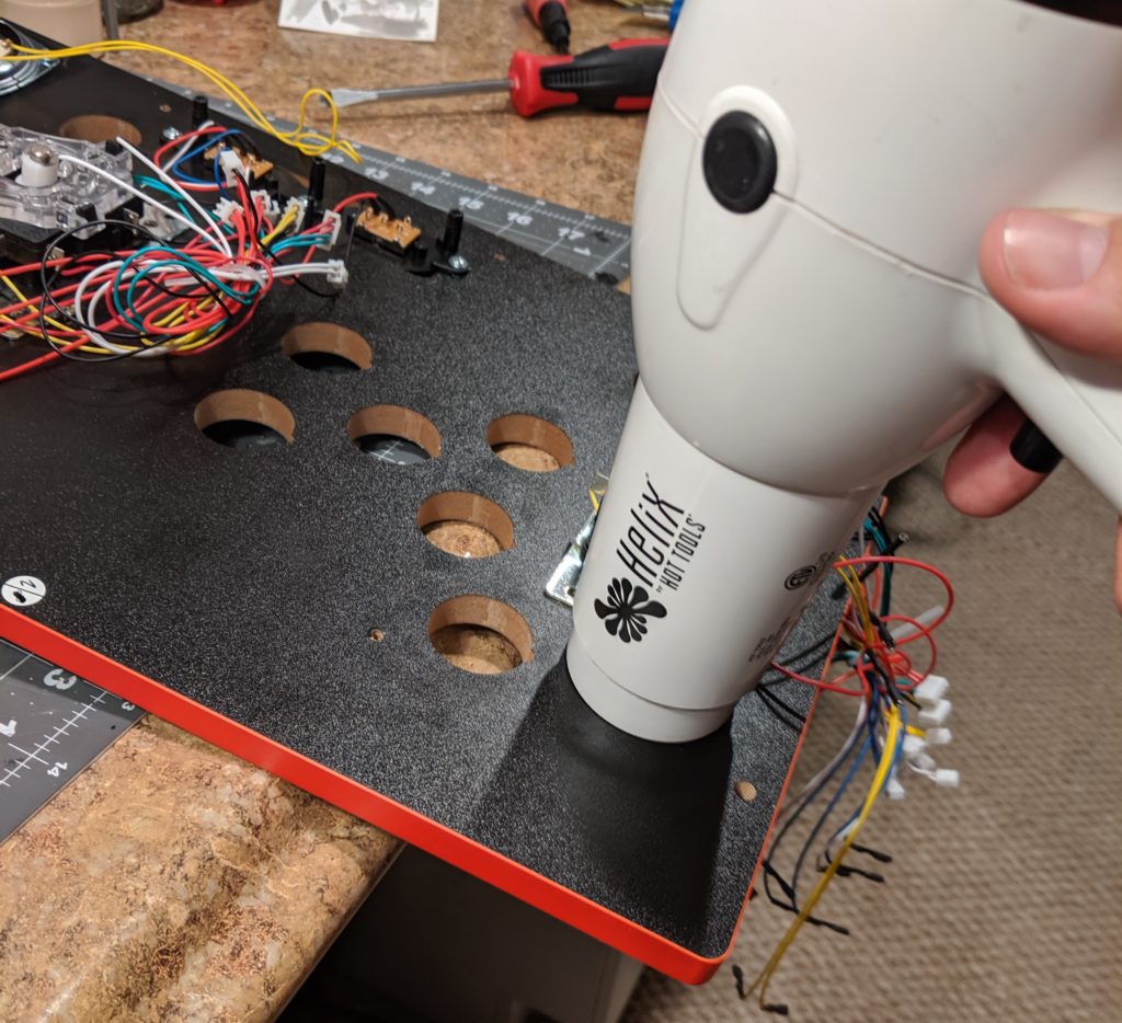
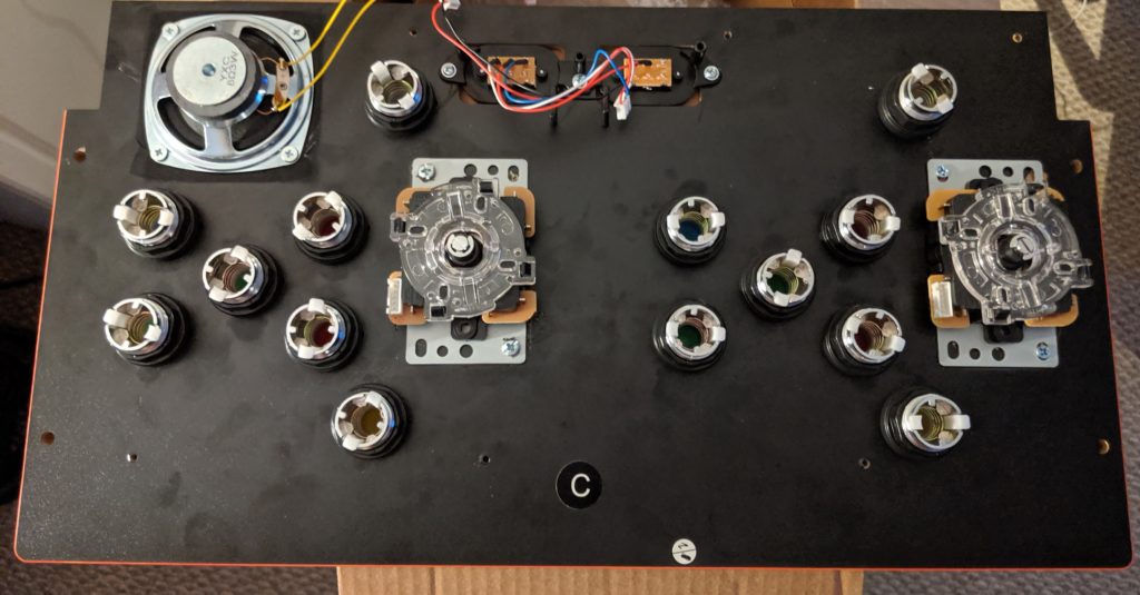
Step 6. Remove the old joysticks. First unscrew the bat top of both joysticks. Remove the screws that connect the metal plate to the board. The metal place is also glued to the board. You need to melt the glue a little so you can pry out these panels out. Here you can use a heat gun or a hair drier.
Blow some hot air directly in the metal panel. The smell of the carcinogenic fumes you are breathing means the glue is now melting.
I would recommend this step in a well ventilated area.
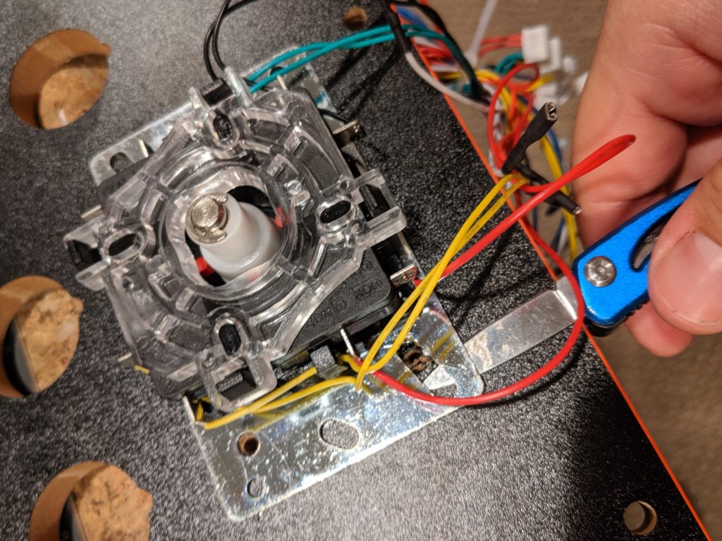
Use a knife or a screwdriver to pry out the metal plate. You can heat a little and pry a little until the whole plate is out.
Melt the glue and pry it out.
For now I’m not removing the speaker and switches.
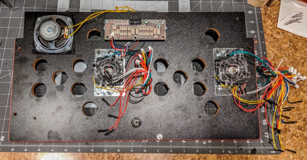
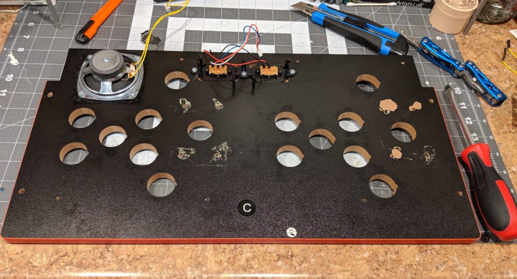
Control deck after I removed the buttons and joysticks.Everything I removed from the control deck so far.
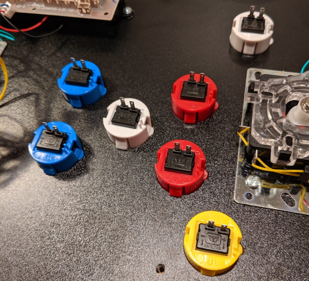
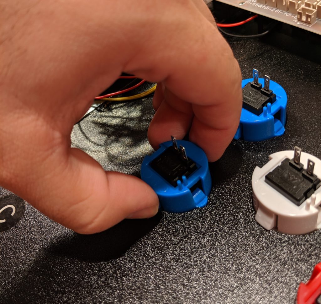
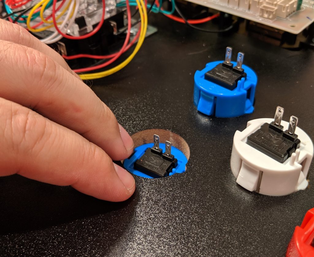
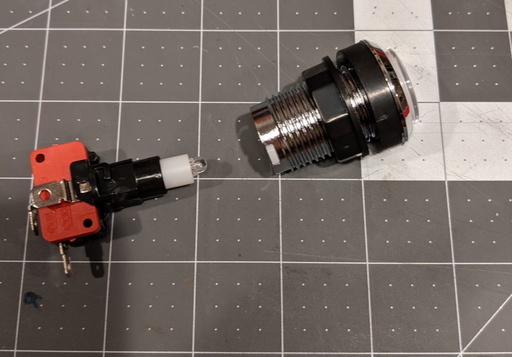
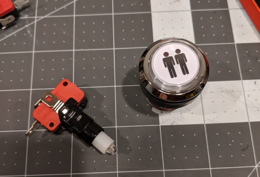
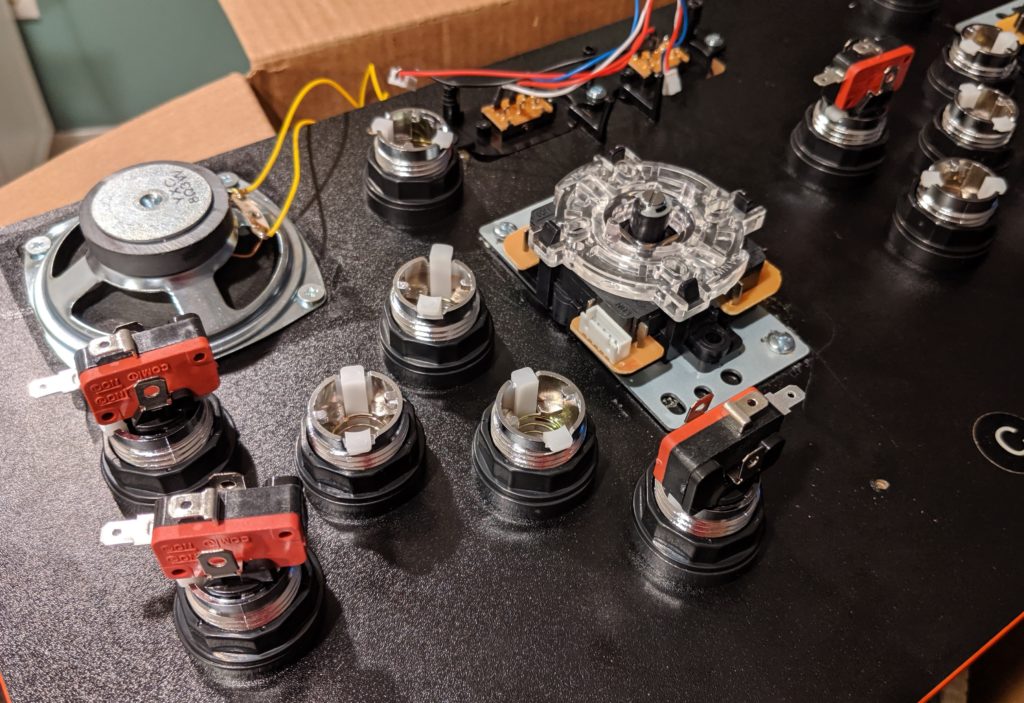
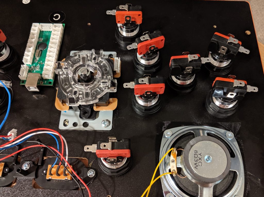
Step 7. Install the new buttons. These buttons are a little bit different from the original ones. They have two pieces, the mechanical part and the connectors and LED. You can separate them by twisting. They also have a plastic nut that help fix them to the board.
New button, side view.News button, top view.
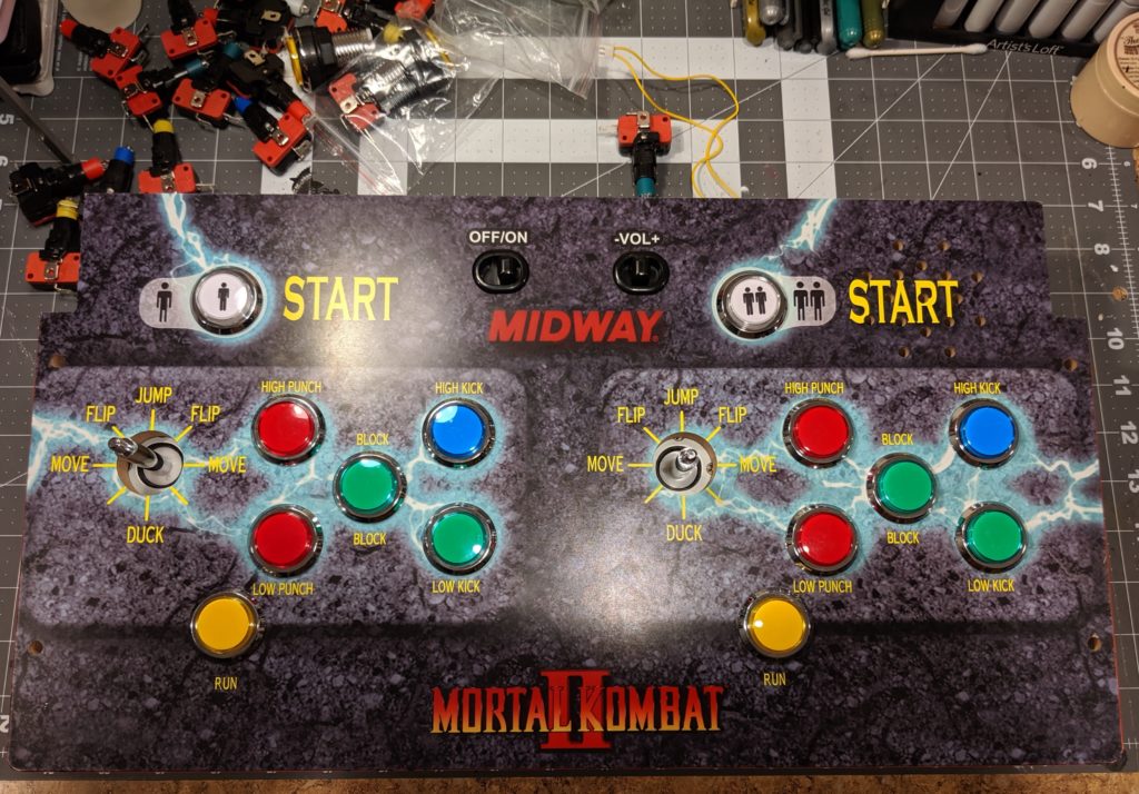
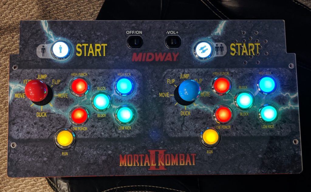
At this step you have the option to choose the color schema for your buttons. I choose something symmetrical. The button assignment is done later in software.
Step 8: Install the joysticks. Remove the bat top from the joystick. Insert it into the panel. Put the screws.
Buttons and joysticks installed
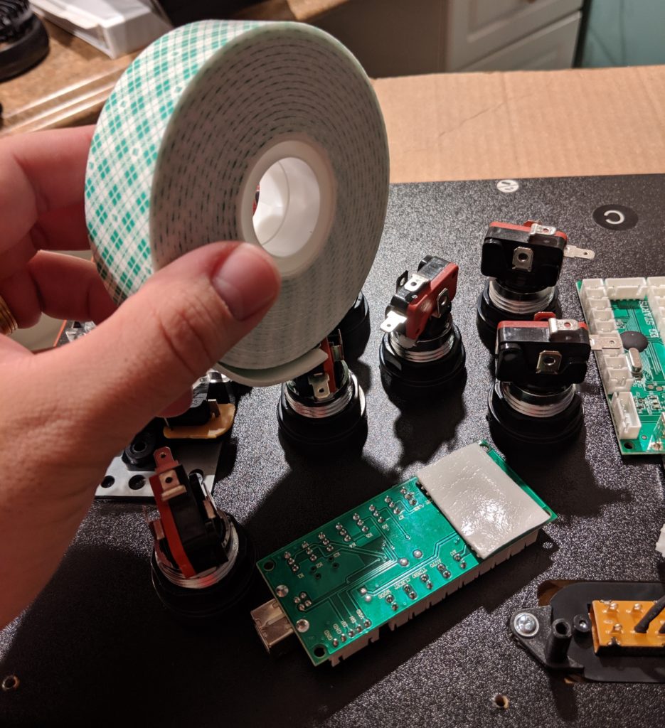
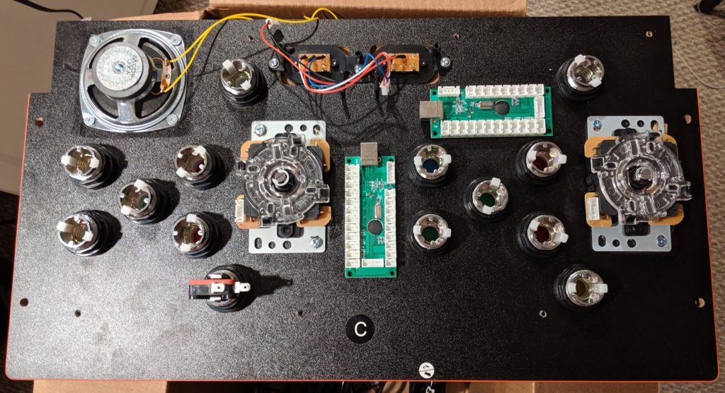
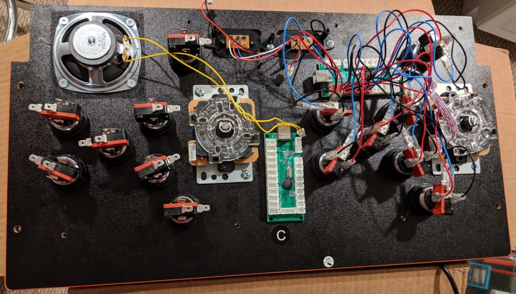
Step 9. Mount the USB control boards. I used Scotch Permanent Mounting Tape for this. Little screws would also do the job. When choosing where to mount them keep in mind the distance between the board and the buttons and also the USB wires.
Boards installed.
Step 10. Assemble the other end of the buttons. Just twist them in place.
Buttons assembled.
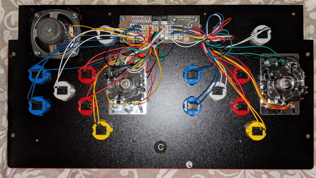
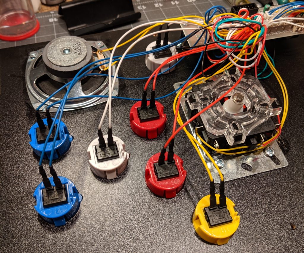
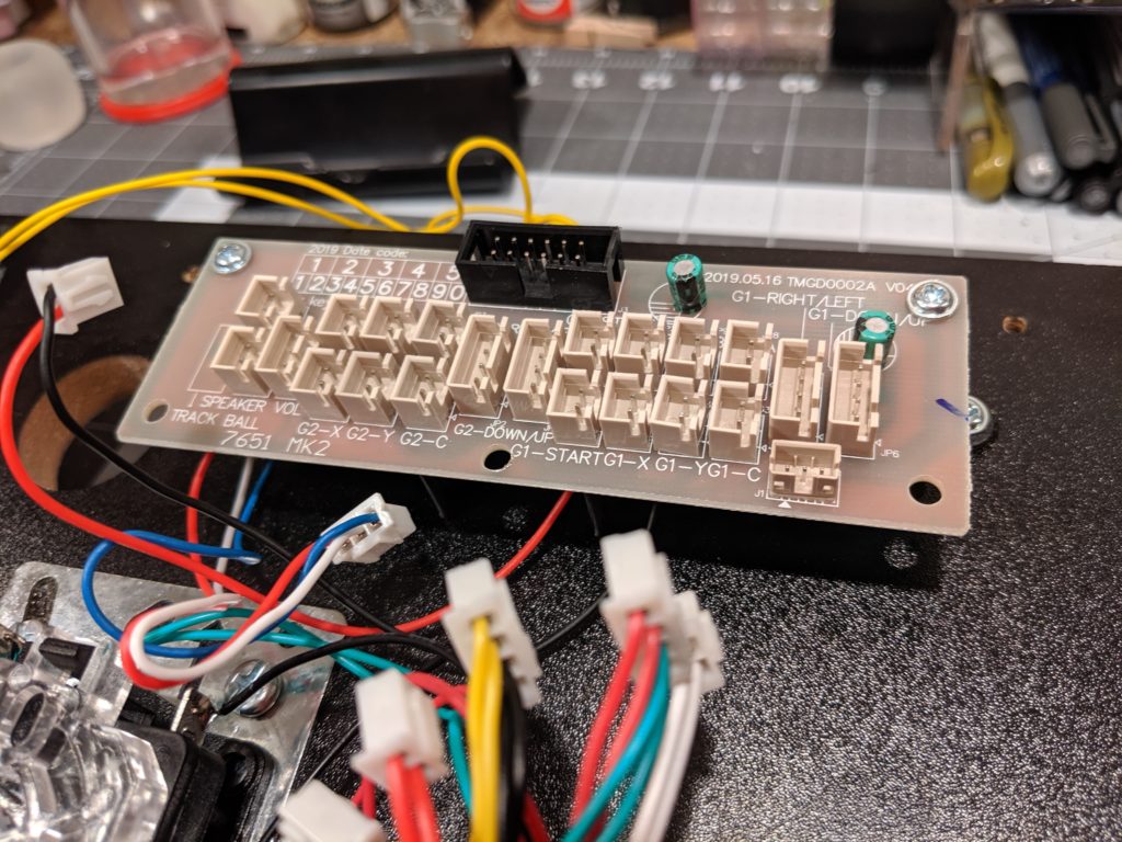
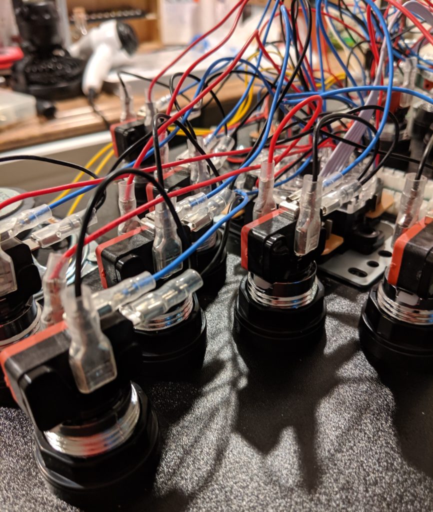
Step 11. Install the wires. Each button will expose four connectors. Check your manual for the proper color schema for the wires. They are different depending on the kit you choose and the kit you get.
The order that you put the connectors in the board is not really important because the configuration will be done later in software.
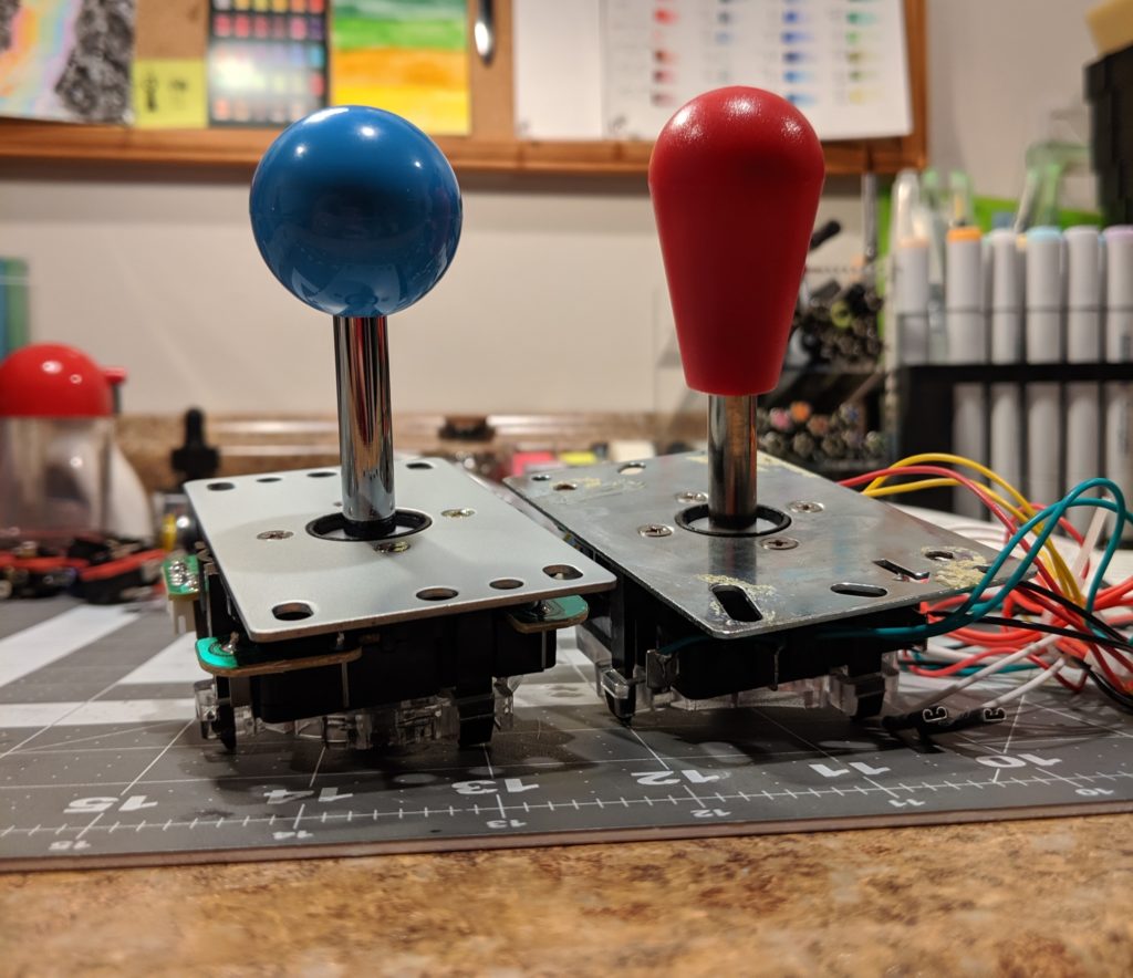
Step 12. Screw the joystick handle back. You can use the new joystick handle but can reuse the old one as well. The new joystick came with a balltop handle (left) and the original joystick had a battop handle. The handle is fixed screwing. You can easily change it latter without need of any tools.
Blue balltop handle (left) in the new joystick and the original joystick with a red battop handle.
Step 13. Testing everything. I this point I would recommend putting the protective plastic case back but secured by only a few screws because you will very likely reopen it soon to fix some buttons.
Plug the two USB cables from the encoding boards to a computer.
The first test is to check if the lights. If a light is not on it is probably because the wires are not correctly connected. If it is not that, then the LED could be failing. My kit came with some extra LEDs and components (but it was not necessary so far).
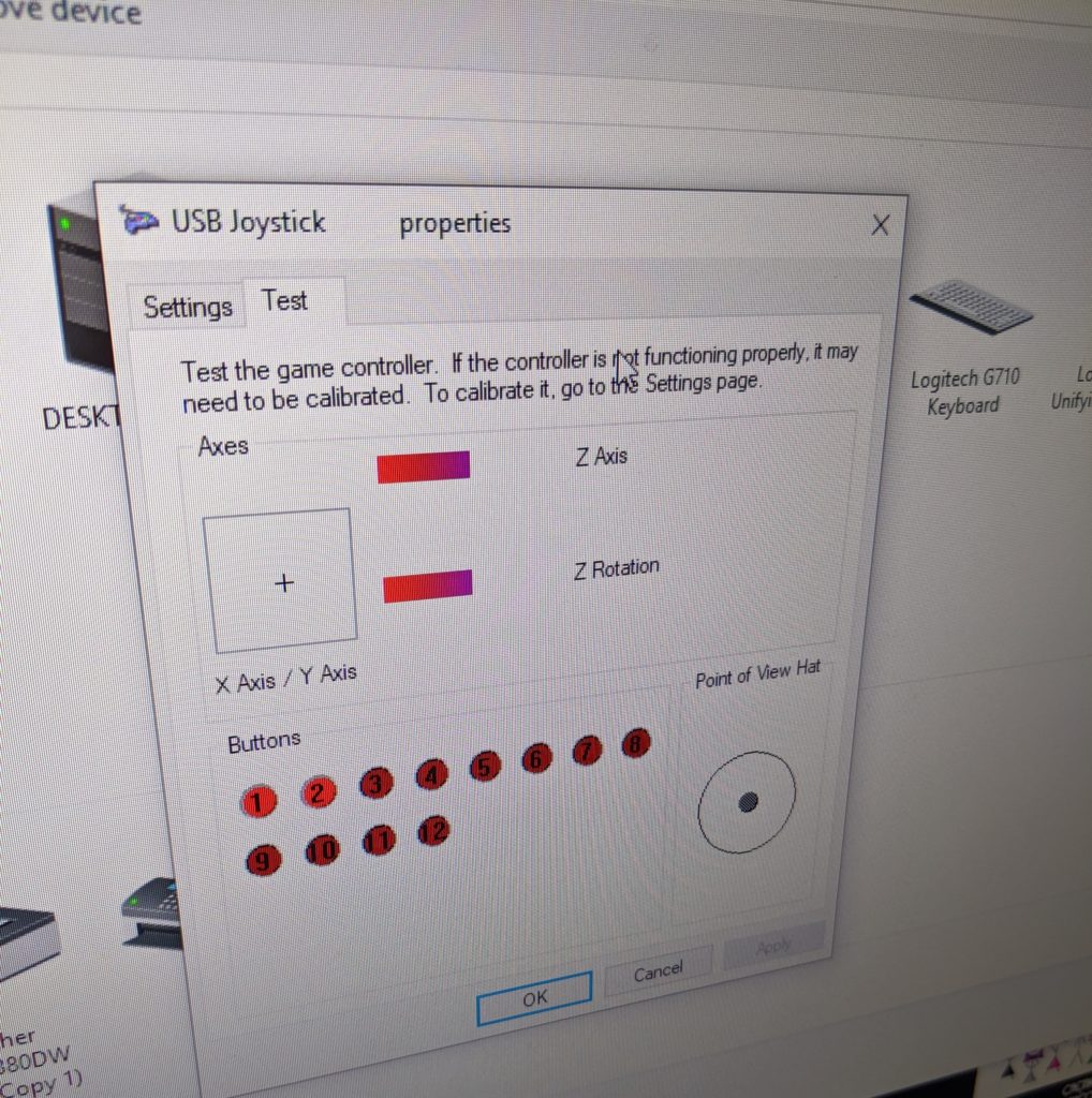
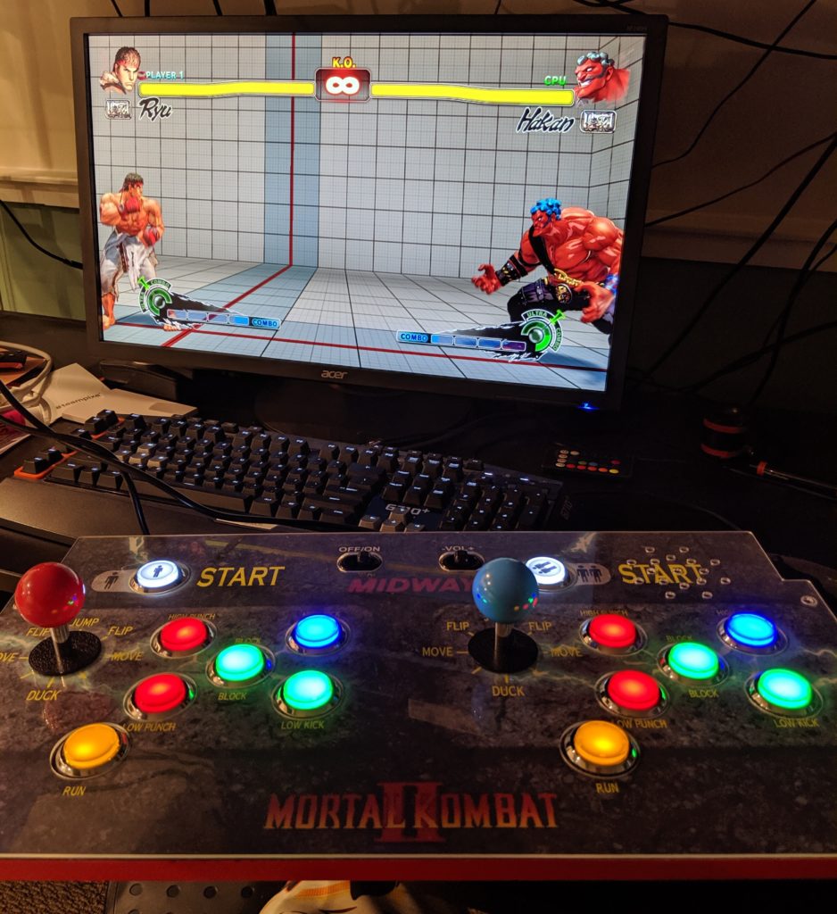
You can also test the whole control deck as two completely functional controls with the PC. Windows should auto-detect the boards as two USB joysticks.
USB Joystick configuration screen.Control deck playing Ultra Street Fighter IV on a PC
Installing the controller board
The original monitor from an Arcade1UP cannot be directly used with a video cable like HDMI. I’m using this kit for this. Make sure the code in the back of the Arcade1UP monitor matches the one in the description of the product.
Step 1. Remove the metal box case with the original board from the monitor. This case holds the mother board of the original Arcade1UP. Remove the cables and remove it from the cabinet.
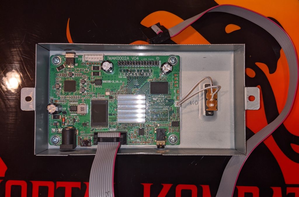
The heart of the MK Arcade1UP.
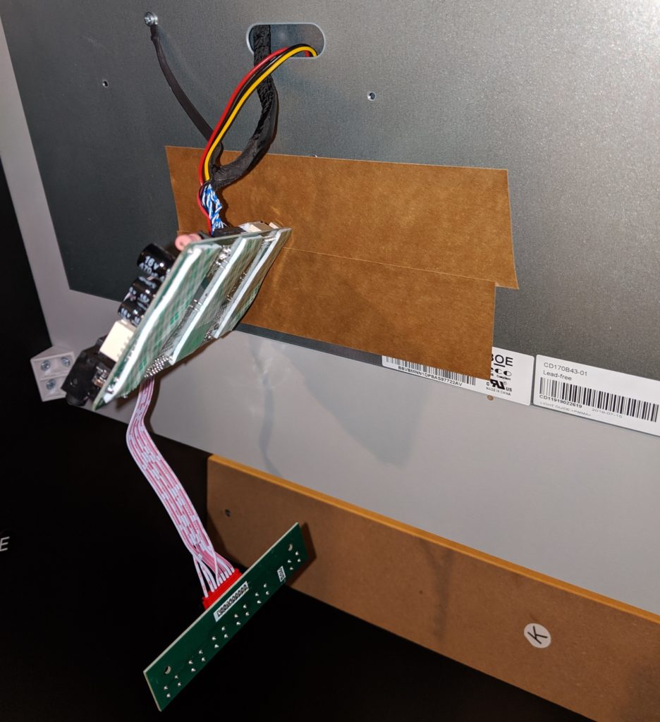
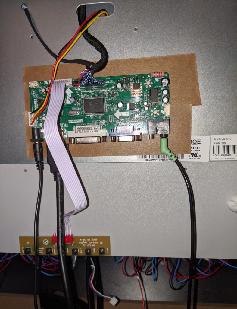
Step 2. Install the new board. I put some tape in the back metal panel of the monitor and used double face tape to fix the new controller board.
The power supply is the same from the original board. This board now receives a video input (HDMI, VGA, VGI) and displays it in the monitor. The smaller board with 6 buttons are like buttons in a TV where you can change volume, brightness, etc.
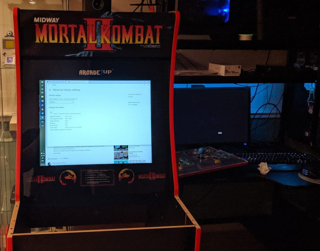
Step 3. Test you can display external video in this monitor. Just grab an HDMI cable from your PC and plug into the controller board. It should just display it like an external monitor.
Arcade1UP monitor connected from the PC
Installing the Raspberry Pi
A Raspberry Pi is pretty much a tiny Linux computer. It has everything on a single package (memory, CPU, motherboard, etc). I’m using RetroPie as a distribution. Retropie comes with everything you need but the actual game ROMs.
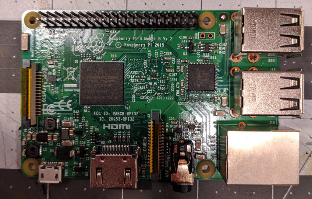
Raspberry Pi 3 Model B
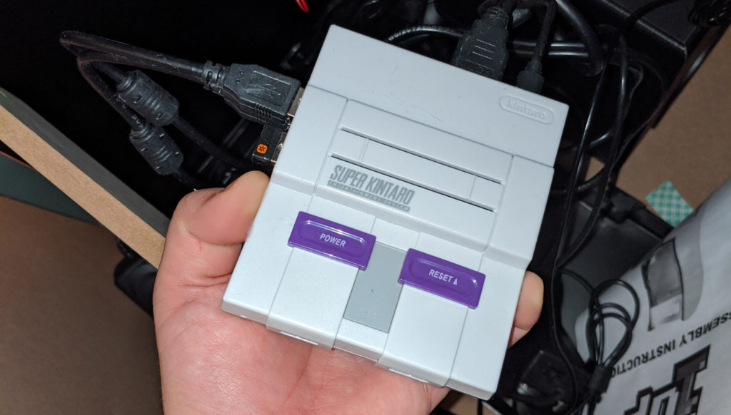
When I was building this I noticed that the Raspberry Pi 3 had the best compatibility and was working well with most of emulators and games. This is likely changing in the future so if I was building another machine now I would check this again. I already had a RPi 3B with a case (Kintaro Super Kuma) from another project.
Raspberry PI with a SNES inspired case
For now I’m not going to put here fine grained details on the RPi installation and configuration. In short, you need to download RetroPie, make a bootable SD card with it, stick it into the RPi and boot it. There are many ways to add games but the most practical one I found was via network using SMB (Samba) at “\\RETROPIE “. Making sure the files are in the correct folders for each emulator. For example rooms for Game Boy should be at “/home/pi/RetroPie/roms/gb/” and for Neo Geo at “/home/pi/RetroPie/roms/neogeo/”.
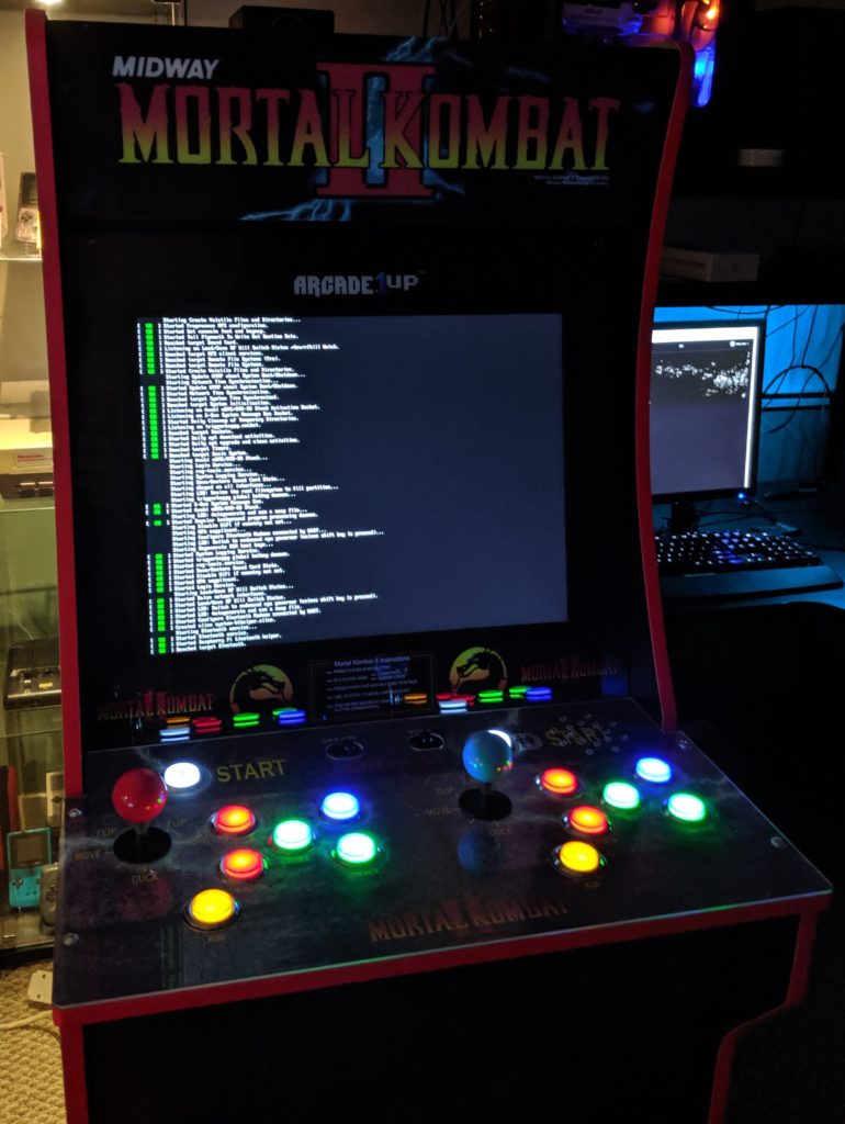
Raspberry Pi booting with Retro Pi
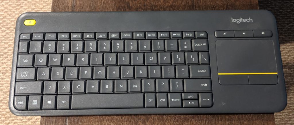
To make the whole process easier I highly recommend using a wireless keyboard like the Logitech K400 Plus that already comes with a touchpad. It’s small, takes only a USB slot and is great keyboard to have around for projects like this. You can press Ctrl + Alt + F2 to access the Raspberry pi terminal (F3 to F6 for TTY3 to TTY6 respectively). Retropie default user is pi and default password is raspberry.
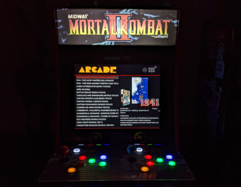
Light up marquee working.Logitech K400+
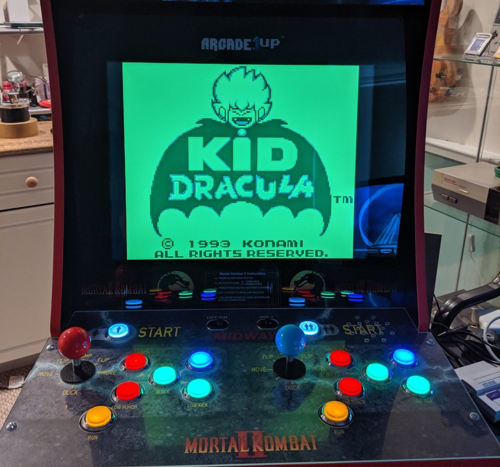
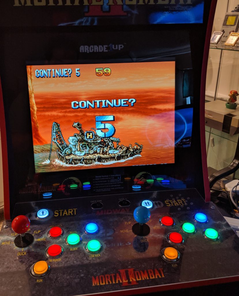
I done my first test with the Game Boy emulator and Kid Dracula. After that worked I moved to test more games.
Kid Dracula. Game Boy, 1993.
When I moved to games with a little bit heavier emulation I started to get this error.
under-voltage detected
The documentation for this said “The undervoltage icon is displayed when the voltage the Pi is receiving drops below 4.65V. “. Indeed, I was using a common USB charger. I then moved to a dedicated charger designed for a RPi that could provide enough current and voltage to power the RPi.
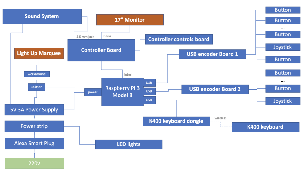
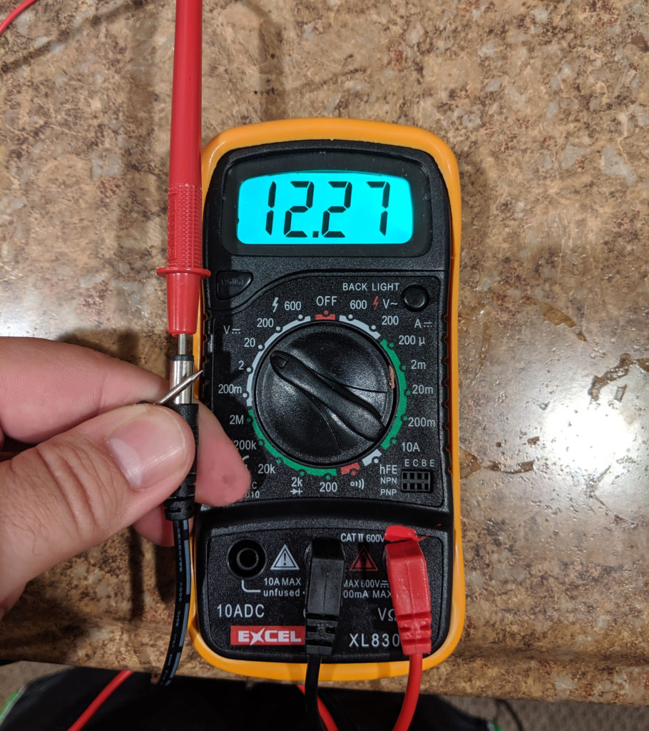
In the original light up marquee was powered by the output of the main board. The original power supply now powers the monitor controller board. I used this splitter cable to send one cable to the controller board and the other the the light up marquee. It’s always worth checking the polarity and voltage of these things.
Testing voltage and polarity.
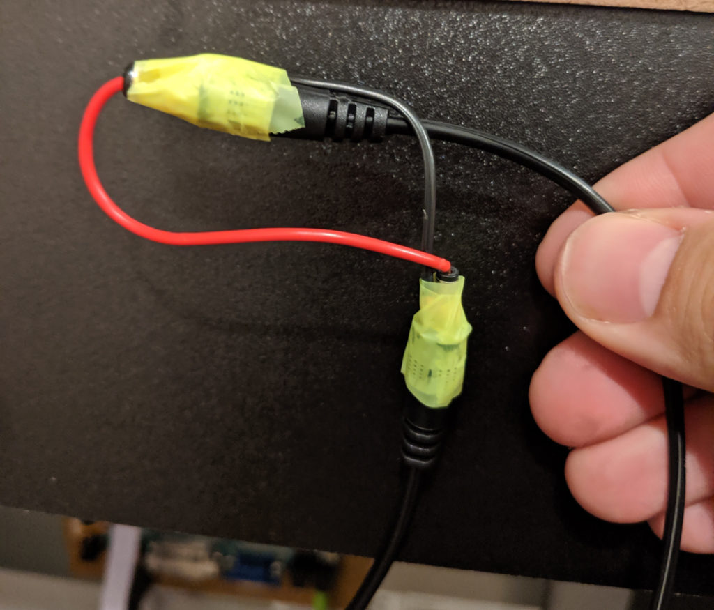
Because the splitter outputs two jack cables (male) and the lightup marquee cable is also a jack I had to do this workaround to connect the two cables. Cutting and reconnecting the cables would also work but I did not want to do that to the marquee cable. Later I will fix this.
“Nothing is more permanent than a temporary solution”, old Russian proverb.All working.
Alexa integration
In front of all this I’m using an Amazon Smart Plug so I can say “Alexa, turn the arcade on” and everything is powered with all the lights and sounds. Other people have reused the on/off switch from the original control deck for this.
Conclusion
At this point this arcade cabinet is fully functional and can play hundreds of games. I’m still doing further modifications and improvements but they will come in future posts.
To discovery which file type you have to use for your image just follow these simple instructions in following priority order:
Have text? Use PNG.
Is a piece of art like a draw, a painting or a webcomic? Use PNG.
It is… moving! Use GIF.
Is a photo? Use JPG.
Is not exactly a photo but contains photos (like people. trees and landscapes)? Use JPG.
Is not a photo, does not contain a photo but I remain concerned about the size of my file despite the breakthrough in telecommunication speeds. Try PNG with indexed palette and Floyd–Steinberg color dithering.
Nah, man. Use JPG but with all lower compression or higher quality options you may find.
It’s nothing listed above! Sir, your problem is far away from the scope of these instructions.
In Inkscape if you have two filled circles. A big solid red one and a smaller, blurred and pinky one, like this: You can use the mask to trap one inside another to create a light effect.
Metaphorically, I drew a mask using the mask effect:
Diariamente, as nove da manhã ele posta qual vai ser o cardápio do RU (Restaurante Universitário) da UFC naquele dia.
Assim, quando vai batendo a hora da fome, os alunos podem entrar no perfil @rudaufc e olhar qual vai ser o prato do dia, ou quem está seguindo ele no Twitter pode ter a agradável surpresa de ver todo dia o que vai ser servido hoje.
Aqui está o código fonte do arquivo rudaufc.sh:
#!/bin/sh
# Twitter bot @rudaufc
login="rudaufc"
senha="suasenhaaqui"

segunda="Picadinho com legumes ou bife na chapa. Salada de macarrão com cenoura. Arroz. Feijão com abóbora e batata doce."
terca="Franco guisado ou coxas de frango ao forno . Salada de acelga, cenoura e passas. Arroz. Feijão com abóbora e batata doce."
quarta="# Feijoada à moda RU ou bisteca . Salada de repolho branco, cenoura e abacaxi. Arroz. Feijão com abóbora e batata doce"
quinta="Frango à passarinho ou frango chinês. Salada de Alface, Tomate e Cebola. Arroz. Feijão com abóbora e batata doce."
sexta="# Isca ao molho ou maravilha de carne. Salada de acelga com cenoura. Arroz. Feijão com abóbora e batata doce."

dia=`(date +%w)`
log=`(date +%Y-%m-%d-%s)`"-$$.log"
dir="/home/silveiraneto/rudaufc"
msg=""
case "$dia" in
#	"0") msg=$domingo ;;
	"1") msg=$segunda ;;
	"2") msg=$terca ;;
	"3") msg=$quarta ;;
	"4") msg=$quinta ;;
	"5") msg=$sexta ;;
#	"6") msg=$sabado ;;
esac

curl -u $login:$senha -d status="$msg" http://twitter.com/statuses/update.xml > $dir/$log
A mágica toda está na capacidade do Curl de acessar facilmente a API do Twitter para enviar mensagens.
Para que o script execute diariamente as nove da manhã ele está alocado em um servidor com a crontab configurada da seguinte maneira:
I got a simple motor from a broken domestic printer. It’s a Mitsumi m355P-9T stepping motor. Any other common stepping motor should fits. You can find one in printers, multifunction machines, copy machines, FAX, and such.
With a flexible cap of water bottle with a hole we make a connection between the motor axis and other objects.
With super glue I attached to the cap a little handcraft clay ox statue.
It’s a representation from a Brazilian folkloric character Boi Bumbá. In some traditional parties in Brazil, someone dress a structure-costume and dances in circular patterns interacting with the public.
Controlling a stepper motor is not difficult. There’s a good documentation on how to that on the Arduino Stepper Motor Tutorial. Basically it’s about sending a logical signal for each coil in a circular order (that is also called full step).
You’ll probably also use a driver chip ULN2003A or similar to give to the motor more current than your Arduino can provide and also for protecting it from a power comming back from the motor. It’s a very easy find this tiny chip on electronics or automotive stores or also from broken printers where you probably found your stepped motor.
With a simple program you can already controlling your motor.
// Simple stepped motor spin
// by Silveira Neto, 2009, under GPLv3 license
// http://silveiraneto.net/2009/03/16/bumbabot-1/
int coil1 = 8;
int coil2 = 9;
int coil3 = 10;
int coil4 = 11;
int step = 0;
int interval = 100;

void setup() {
  pinMode(coil1, OUTPUT);
  pinMode(coil2, OUTPUT);
  pinMode(coil3, OUTPUT);
  pinMode(coil4, OUTPUT);
}

void loop() {
  digitalWrite(coil1, step==0?HIGH:LOW);
  digitalWrite(coil2, step==1?HIGH:LOW);
  digitalWrite(coil3, step==2?HIGH:LOW);
  digitalWrite(coil4, step==3?HIGH:LOW);
  delay(interval);
  step = (step+1)%4;
}
Writing a little bit more generally code we can create function to step forward and step backward.
My motor needs 48 steps to run a complete turn. So 360º/48 steps give us 7,5º per step. Arduino has a simple Stepper Motor Library but it doesn’t worked with me and it’s also oriented to steps and I’d need something oriented to angles instead. So I wrote some routines to do that.
For this first version of BumbaBot I mapped angles with letters to easy the communication between the programs.
Notice that it’s not the final version and there’s still some bugs!
// Stepped motor control by letters
// by Silveira Neto, 2009, under GPLv3 license
// http://silveiraneto.net/2009/03/16/bumbabot-1/
int coil1 = 8;
int coil2 = 9;
int coil3 = 10;
int coil4 = 11;
int delayTime = 50;
int steps = 48;
int step_counter = 0;
void setup(){
pinMode(coil1, OUTPUT);
pinMode(coil2, OUTPUT);
pinMode(coil3, OUTPUT);
pinMode(coil4, OUTPUT);
Serial.begin(9600);
}
// tells motor to move a certain angle
void moveAngle(float angle){
int i;
int howmanysteps = angle/stepAngle();
if(howmanysteps<0){
howmanysteps = - howmanysteps;
}
if(angle>0){
for(i = 0;i




 You can use the mask to trap one inside another to create a light effect.